Shane Clarkson
Josh Feler
Jacob Gowan
Joy Xi
Josh Feler
Jacob Gowan
Joy Xi
Final Project Documentation
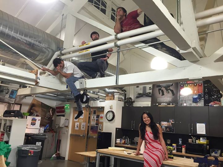
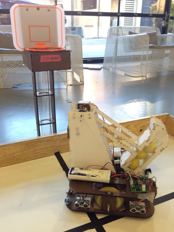
Figure 1: Team 12-Inch Grave in action!
Introduction:
For this year’s ME210 final project, we were to construct a robot which could collect and maintain possession of three small foam balls at a time and proceed to score by directing them into one of three hoops. The hoop on our side of the arena was worth one point, while the two hoops across from our arena were worth two and three points. For simplicity, our group determined that we would begin by working to enable our ‘bot to ‘dunk’ on the one-point hoop and enhance our ‘bot to shoot on the other hoops if time permitted. Following is an exploration of our solution to this challenge!
Subsystems:
The first system we implemented was a rotary encoder circuit through our Arduino for our two-wheeled robot. This system can detect the number of holes going by as each wheel turns, and thus can help us both to keep track of distance travelled and to maintain movement on a straight line. (As an aside, the tape sensing circuit is identical to the encoder circuit, but with different threshold values.) Additionally, we experimented with and prototyped the dunking arm that we will use to score on the one-point basket. Initially, this is simply a rigid arm with a cup to hold the balls attached to one end, and a servo attached to the other, which lifts the arm through the appropriate angle to ‘dunk’ the balls (see Figure 2).
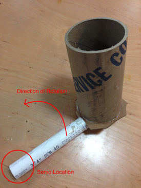
Figure 2: Dunking arm prototype
Calculations:
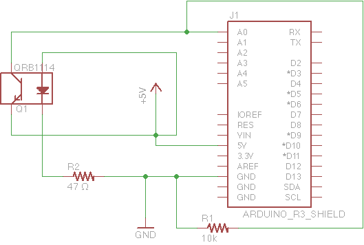
Figure 3 shows the calculations performed to determine resistor values for our rotary encoder circuit. Utilizing the closest resistance values available to us in our lab kits yields R1 = 10 kΩ and R2 = 47 Ω.
Figure 3 shows the calculations performed to determine resistor values for our rotary encoder circuit. Utilizing the closest resistance values available to us in our lab kits yields R1 = 10 kΩ and R2 = 47 Ω.
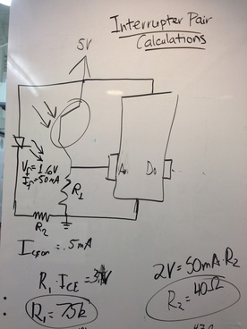
Figure 3: Encoder circuit calculations
Figure 4 shows the calculations performed to determine the maximum amount of torque we will require from our servo in order to properly (and safely) lift the arm and dunk the balls. For our prototype, the values for mass of the arm, m = 10 oz = 0.283 kg, and the length of the arm, r = 10 in. = 0.254 m, yield T = 100 oz*in = 0.704 N.
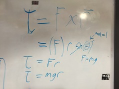
Figure 4: Torque calculations
System block diagram:
The state diagram describes how all of our robot’s states interact with each other and how one action can direct the ‘bot to a new state. This diagram lays the foundation for our operation, and thus was one of the very first tasks we completed in working on our robot. Figure 5 shows our first iteration of the state diagram.
The state diagram describes how all of our robot’s states interact with each other and how one action can direct the ‘bot to a new state. This diagram lays the foundation for our operation, and thus was one of the very first tasks we completed in working on our robot. Figure 5 shows our first iteration of the state diagram.
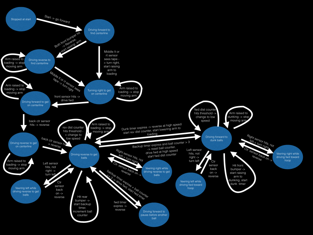
Figure 5: Initial state diagram for our robot
Preliminary testing results:
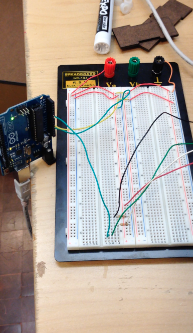
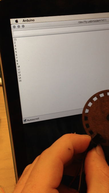
Below is a link to a short video that captures the Arudino and its circuit, as well as the encoder itself and the serial monitor output, as it counts the holes. Figures 6 and 7 are screenshots captured from the video depicting the physical implementation of the circuit and the encoder with the Arduino serial monitor output, respectively. Additionally, Figure 8 shows a schematic diagram of the circuit, created in Eagle.
https://www.youtube.com/watch?v=tvMWjQU4reI&feature=youtu.be
Progress Check:
With construction of our robot underway, we plan to continue implementing and testing our subsystems until we achieve our minimum viable prototype, which will be able to navigate the arena and dunk multiple balls. We have ordered motors already, and will be getting other necessary parts ordered and/or picked up shortly. With parts in hand, nothing will stop us from rapidly creating our first full-system prototype!
Implementing Subsystems:
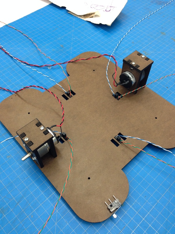
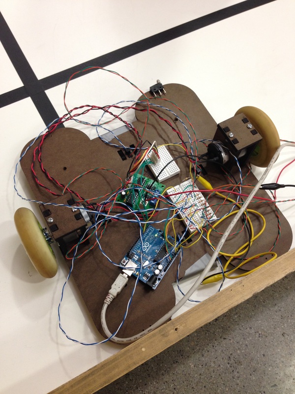
As we continued building our robot, we aimed to implement the driving, tape-sensing, bumping, and dunking functions simultaneously. Thus, we began by creating SolidWorks files for the base of our robot as well as mounting “boxes” for our motors, and proceeded to laser cut these parts. Figure 9 shows the motors inside the mounts and attached to the robot base. Additionally, the tape sensors sit in the cut-outs on the front, back, and both sides of the base, and are wired to our designed circuit. Later, we attached bumpers to the front and back of our robot, to sense whether it had hit into a wall. Finally, we implemented the dunking function using our prototyped dunking arm attached to a servo. Figure 10 shows the assembled prototype, with wheels attached, tape sensors hooked up to the circuit, a single bumper attached to the front right of the robot, and the Arduino powering the necessary components.
With construction of our robot underway, we plan to continue implementing and testing our subsystems until we achieve our minimum viable prototype, which will be able to navigate the arena and dunk multiple balls. We have ordered motors already, and will be getting other necessary parts ordered and/or picked up shortly. With parts in hand, nothing will stop us from rapidly creating our first full-system prototype!
Implementing Subsystems:
As we continued building our robot, we aimed to implement the driving, tape-sensing, bumping, and dunking functions simultaneously. Thus, we began by creating SolidWorks files for the base of our robot as well as mounting “boxes” for our motors, and proceeded to laser cut these parts. Figure 9 shows the motors inside the mounts and attached to the robot base. Additionally, the tape sensors sit in the cut-outs on the front, back, and both sides of the base, and are wired to our designed circuit. Later, we attached bumpers to the front and back of our robot, to sense whether it had hit into a wall. Finally, we implemented the dunking function using our prototyped dunking arm attached to a servo. Figure 10 shows the assembled prototype, with wheels attached, tape sensors hooked up to the circuit, a single bumper attached to the front right of the robot, and the Arduino powering the necessary components.
Driving:
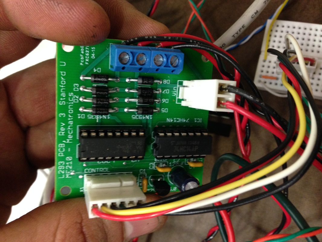
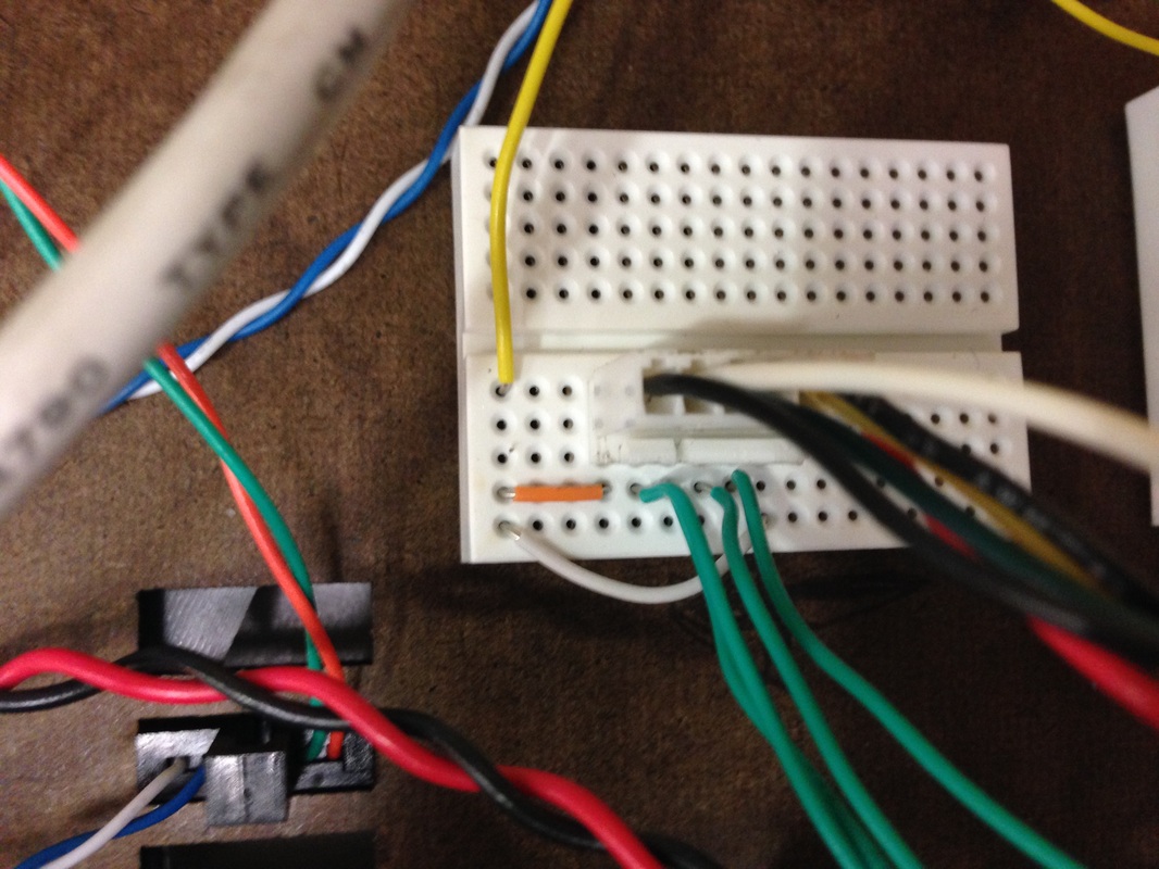
In order to drive our robot, we utilized an L293 PCB with dual H-bridges. We supplied this chip with +15V power (via two +7.5V batteries in series) to V_in, and then utilized the J1 diodes to supply each motor with the necessary information. For each motor, we had an Enable and a Direction wire, which we connected to the Arduino. To ease this process, we created a 6-pin Molex connector for the L293. Transferring these connections to a small nearby breadboard, we then grounded the outer two pins, and connected Enable and Direction for the left and right motors to digital output pins 2, 3, 4, and 5 of the Arduino, respectively, with 51 kΩ pull-down resistors for each. Figure 11 illustrates the L293 chip and the aforementioned connections, while Figure 2 shows the small breadboard and subsequent connections to the Arduino (resistors not pictured).
In order to drive our robot, we utilized an L293 PCB with dual H-bridges. We supplied this chip with +15V power (via two +7.5V batteries in series) to V_in, and then utilized the J1 diodes to supply each motor with the necessary information. For each motor, we had an Enable and a Direction wire, which we connected to the Arduino. To ease this process, we created a 6-pin Molex connector for the L293. Transferring these connections to a small nearby breadboard, we then grounded the outer two pins, and connected Enable and Direction for the left and right motors to digital output pins 2, 3, 4, and 5 of the Arduino, respectively, with 51 kΩ pull-down resistors for each. Figure 11 illustrates the L293 chip and the aforementioned connections, while Figure 2 shows the small breadboard and subsequent connections to the Arduino (resistors not pictured).
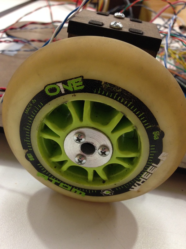
To make our robot mobile, we attached a standard in-line skate wheel to each 0.25 mm D-shaped motor shaft. This was facilitated by our manufacturing of two-piece aluminum hubs, which fit inside the center of the wheel, and are held in place with a set screw. Figure 13 shows the outside of the wheel, with the outer hub visible, while Figure 14 shows a front view, with the motor shaft and its connection to the wheel visible.

Tape-Sensing:
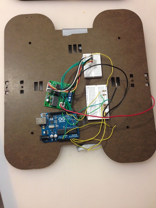
In order to sense the tape and have our robot react appropriately, we added tape sensors to the front, back, and both sides of our robot. These sensors were hooked up to a breadboard in a circuit literally identical to that which we employed for our encoder. The physical implementation of the circuit(s) is shown in Figure 15. (Note that we have four iterations of the circuit, one for each sensor, and that the Arduino supplies the necessary +5V power.) Additionally, Figure 16 shows the EAGLE schematic for the circuit. Initially, we imagined that we would use a value of 27 kΩ for R1; however, after testing, we found that 10 kΩ was a better choice to regulate voltage. The Pin_Out wire represents a connection to the Arduino; the front, left, rear, and right tape sensors connect to analog input pins A0, A1, A2, and A3 of the Arduino, respectively. Figure 17 depicts the Arduino and the aforementioned connections. We also utilized comparators to clean up the signals from the tape sensor. The circuit we created to achieve this task is shown in Figure 18.
In order to sense the tape and have our robot react appropriately, we added tape sensors to the front, back, and both sides of our robot. These sensors were hooked up to a breadboard in a circuit literally identical to that which we employed for our encoder. The physical implementation of the circuit(s) is shown in Figure 15. (Note that we have four iterations of the circuit, one for each sensor, and that the Arduino supplies the necessary +5V power.) Additionally, Figure 16 shows the EAGLE schematic for the circuit. Initially, we imagined that we would use a value of 27 kΩ for R1; however, after testing, we found that 10 kΩ was a better choice to regulate voltage. The Pin_Out wire represents a connection to the Arduino; the front, left, rear, and right tape sensors connect to analog input pins A0, A1, A2, and A3 of the Arduino, respectively. Figure 17 depicts the Arduino and the aforementioned connections. We also utilized comparators to clean up the signals from the tape sensor. The circuit we created to achieve this task is shown in Figure 18.
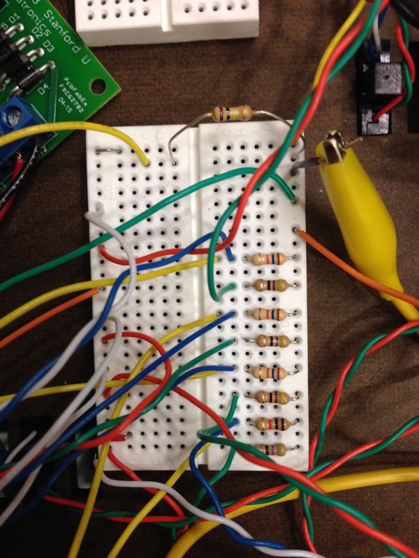
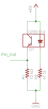
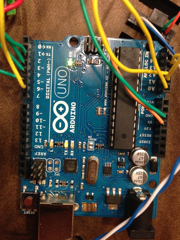
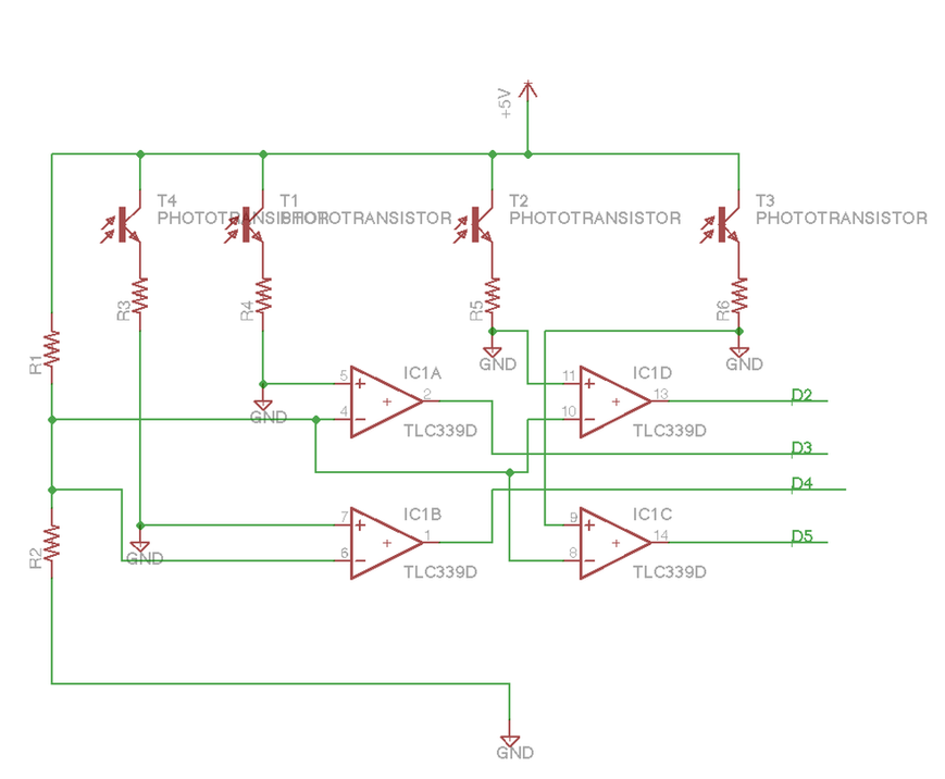
Figure 18: The Comparator circuit that we built to clean up the signals from our tape sensors
Bumping:
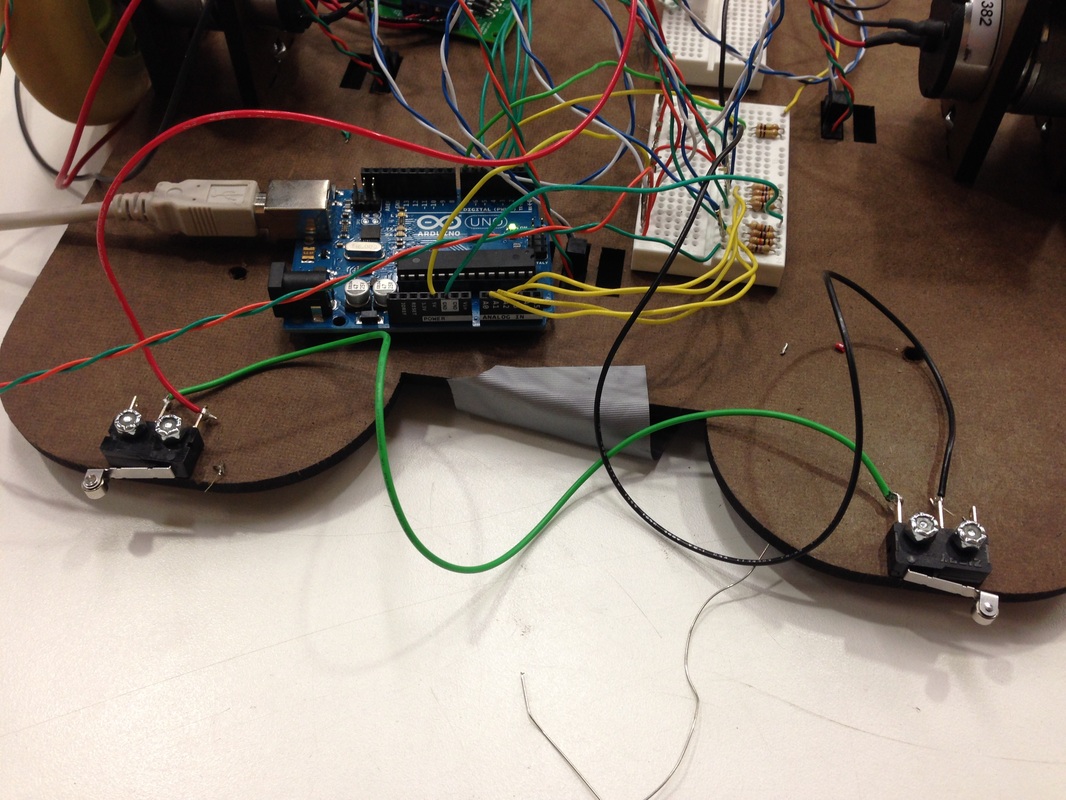
To ensure our robot doesn’t get stuck on a wall, we attached two bump sensors to the front and back of the robot. These sensors return a signal when they are depressed, and thus can inform us when the robot’s path is obstructed. The front bumpers are shown physically connected in Figure 19, while Figure 20 shows a schematic of the circuit drawn in EAGLE (the Switch_SPDT element represents the bumper switch). The Pin_Out wire again represents a connection to the Arduino: this time, the front and rear bumper circuits connect to digital output pins 6 and 7 of the Arduino, respectively.
To ensure our robot doesn’t get stuck on a wall, we attached two bump sensors to the front and back of the robot. These sensors return a signal when they are depressed, and thus can inform us when the robot’s path is obstructed. The front bumpers are shown physically connected in Figure 19, while Figure 20 shows a schematic of the circuit drawn in EAGLE (the Switch_SPDT element represents the bumper switch). The Pin_Out wire again represents a connection to the Arduino: this time, the front and rear bumper circuits connect to digital output pins 6 and 7 of the Arduino, respectively.

Dunking:
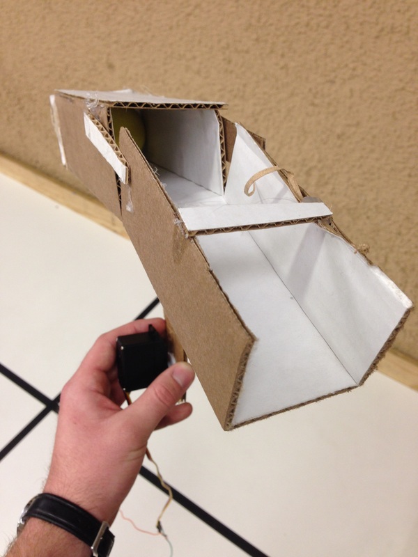
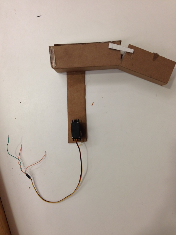
Finally, to score points for our robot, we implemented a dunking arm for the 1-point basket on our side of the arena. This mechanism works by attaching a servo to control the position of our prototype dunking arm. The servo itself requires only three connections: power, ground, and Arduino. For our case, the servo is connected to power and ground from the Arduino as well as digital output pin 13 of the Arduino. The arm has three positions: initialized, loading, and dunking. Its position is controlled by our code, which utilizes the built-in servo.h library. Figure 21 reveals a perspective of the dunking arm prototype, and Figure 22 shows the arm with the servo attached to its base. The dunking arm is triggered to its different positions based on the bumper hits.
Finally, to score points for our robot, we implemented a dunking arm for the 1-point basket on our side of the arena. This mechanism works by attaching a servo to control the position of our prototype dunking arm. The servo itself requires only three connections: power, ground, and Arduino. For our case, the servo is connected to power and ground from the Arduino as well as digital output pin 13 of the Arduino. The arm has three positions: initialized, loading, and dunking. Its position is controlled by our code, which utilizes the built-in servo.h library. Figure 21 reveals a perspective of the dunking arm prototype, and Figure 22 shows the arm with the servo attached to its base. The dunking arm is triggered to its different positions based on the bumper hits.
Progress Check:
As of this check-in, we are following our planned schedule decently well. With all of the subsystems working properly on our prototype, we are ready to move forward by integrating all of these systems and finalizing our design so that we can begin working on the last iteration of our robot!
Redesigns:
Upon completion of our individual subsystems, we continued to test and refine our overall design as well as integrate the subsystems smoothly. Based on our test results, there were a few tweaks that we employed in our pursuit of a better ‘bot. Our updates are described below.
Body:
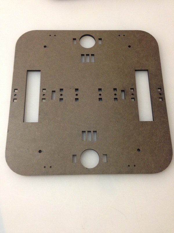
The main re-designs we investigated pertained to the body of our robot. Because our driving and tape-sensing systems proved more unstable than anticipated, we decided to improve our robot by relocating the wheels to inside of the base, rather than their previous position of protruding from the body. This entailed moving the motor mounts closer together toward the middle of the robot. To visualize this change, compare Figures 23 and 24, which show the previous and current motor mount positions on the body, respectively. This change also helped to trim the length of our ‘bot to within a foot.
As of this check-in, we are following our planned schedule decently well. With all of the subsystems working properly on our prototype, we are ready to move forward by integrating all of these systems and finalizing our design so that we can begin working on the last iteration of our robot!
Redesigns:
Upon completion of our individual subsystems, we continued to test and refine our overall design as well as integrate the subsystems smoothly. Based on our test results, there were a few tweaks that we employed in our pursuit of a better ‘bot. Our updates are described below.
Body:
The main re-designs we investigated pertained to the body of our robot. Because our driving and tape-sensing systems proved more unstable than anticipated, we decided to improve our robot by relocating the wheels to inside of the base, rather than their previous position of protruding from the body. This entailed moving the motor mounts closer together toward the middle of the robot. To visualize this change, compare Figures 23 and 24, which show the previous and current motor mount positions on the body, respectively. This change also helped to trim the length of our ‘bot to within a foot.
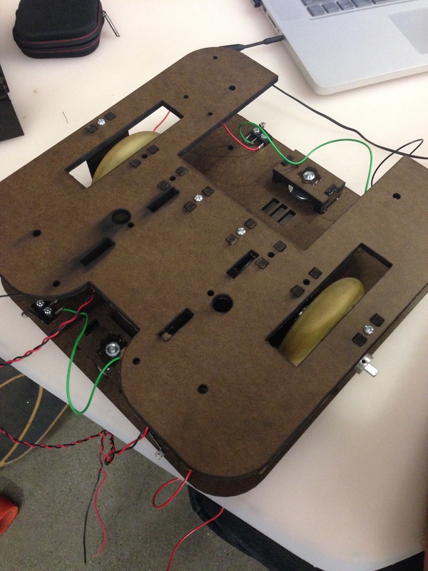
In addition to relocating the motor mounts, we added a wheel mount to each side of each wheel. The wheel mounts are very similar to the motor mounts, and all of the mounts attach above to a second-level of the base, which itself is similar to the lower-level, but with one end removed to make room for the shooting arm (see Figure 25).
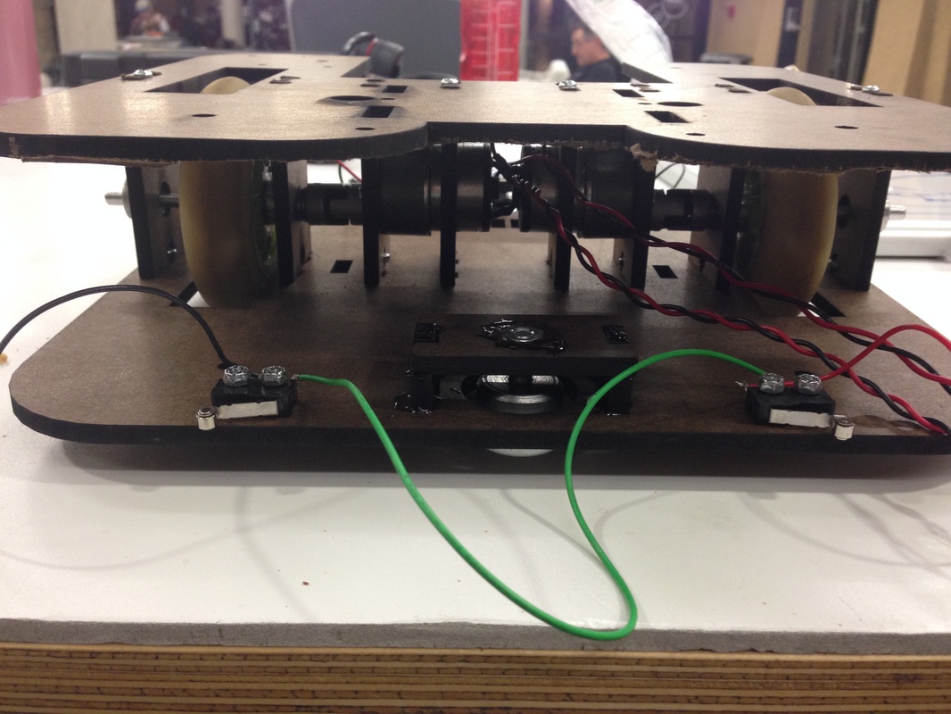
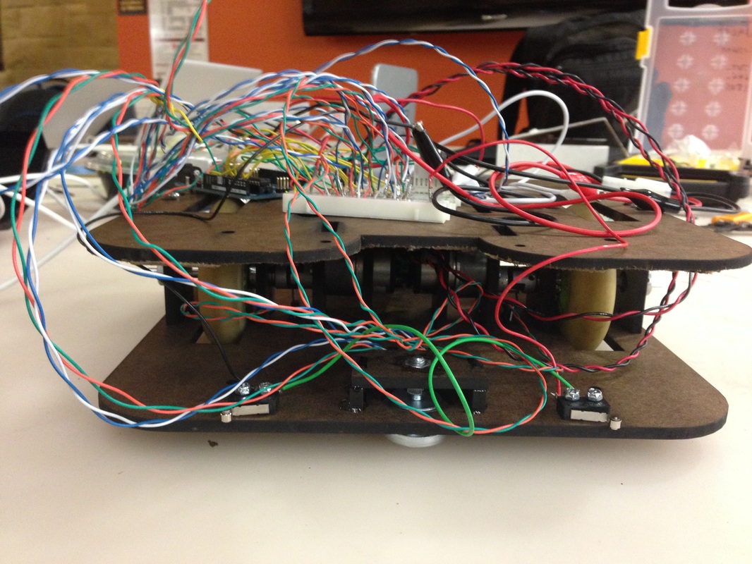
Based on our previous design, however, moving the motor mounts meant we had to also shift the electronic components. This realization led to our design of a second-level of the robot body, where we could easily fit all the components. The second level also helps to add stability to the base as a whole. Finally, to fully constrain our robot’s motion, we added casters to the front and back (the holes for these can seen at the top and bottom of Figure 24 above). Figure 26 shows a side view of the robot base, with both levels, and the attachment of the wheels, motors, and their mounts clearly visible.
With all of these additions and modifications, our robot became much more stable and precise in its driving and tape-sensing capabilities.
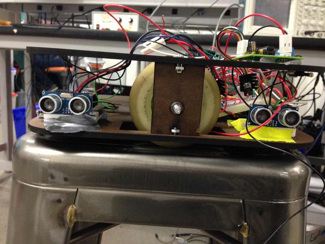
As we continued to design, redesign, and troubleshoot, however, we ultimately realized that the tape-sensing function was still not consistent enough (except in the sense that it was consistently holding us back!), and simply not feasible to implement within our remaining timeline. (Figure 27 shows how convoluted the circuitry became in trying to implement six different tape sensors.) Our next approach involved using encoders to ensure the wheels spun at the same rate. While we were able to properly implement measures to read (and sometimes react to) our encoder values, the inconsistency in the motors still prevented us from driving straight. So we finally bit the bullet and disassembled our robot, replacing both motors with new, presumably more consistent motors. Though the encoders probably were not our fundamental issue, we ultimately decided to try something new and utilized ultrasonic sensors to detect our distance from the side wall and make appropriate turns to center the robot based on those measurements. Attaching an ultrasonic sensor to both the front and back half of our robot also allowed us to ensure we were parallel to the side wall to aid our maneuvering. Figure 28 shows a side view and Figure 29 shows a perspective view of our robot, with both ultrasonic sensors visible in both pictures.
Circuitry:
Adding another level to the base of our robot allowed us to get creative in implementing our circuits for the robot’s systems. We took advantage of the through-holes we cut into the upper level of our ‘bot by threading wires through them when necessary in order to clean up our system as much as possible. During our assembly, we learned the hard way that breadboards do not detach after being stuck down onto a surface! (See Figure 30) To provide the necessary power to all of our components, we hooked up our two 7.5V batteries in series. Additionally, in order to ensure our voltages were exactly what we expected them to be, we added voltage regulators between the batteries and the Arduino as well as between the batteries and the motors.
Adding another level to the base of our robot allowed us to get creative in implementing our circuits for the robot’s systems. We took advantage of the through-holes we cut into the upper level of our ‘bot by threading wires through them when necessary in order to clean up our system as much as possible. During our assembly, we learned the hard way that breadboards do not detach after being stuck down onto a surface! (See Figure 30) To provide the necessary power to all of our components, we hooked up our two 7.5V batteries in series. Additionally, in order to ensure our voltages were exactly what we expected them to be, we added voltage regulators between the batteries and the Arduino as well as between the batteries and the motors.
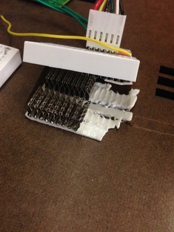
Figure 30: Inside a bread board
The ultrasonic sensors were relatively simple to implement, as they only required two signals (trigger and echo), in addition to power and ground inputs. These sensors are located on the left side of the lower level of our ‘bot, one in the front and one in the rear, both facing sideways (see Figures 28 and 29 above). We controlled them using digital pins 9 and 10 (front) and 11 and 13 (rear) of the Arduino for trigger and echo, respectively. With sensors close to the front and rear of our ‘bot, we were able to use the difference in their measured distance to the wall to veer in the proper direction to orient ourselves parallel to the wall and centered in the court (based on the known, unchanging dimensions of the arena).
Implementing and calibrating these sensors allowed us to finally achieve consistency in our driving direction and motion. With this obstacle overcome, all of our other systems fell into place, and our robot was ready for final testing and assembly.
Integration and Troubleshooting:
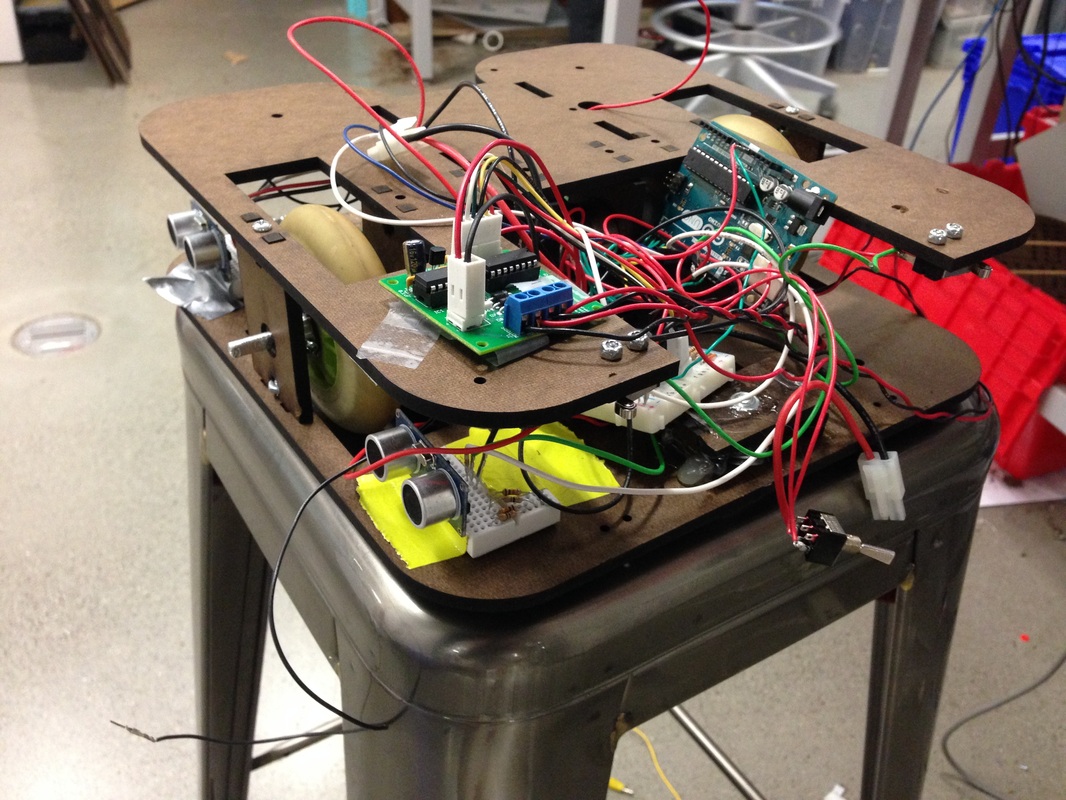
After our robot finally complied with our attempts to make it drive straight, we proceeded to attach the dunking arm and hook up the corresponding servo circuit. Since we had already worked out the kinks with this mechanism, the implementation process was quite straightforward. Figure 31 depicts the robot with the main subsystems attached and functional.
Implementing and calibrating these sensors allowed us to finally achieve consistency in our driving direction and motion. With this obstacle overcome, all of our other systems fell into place, and our robot was ready for final testing and assembly.
Integration and Troubleshooting:
After our robot finally complied with our attempts to make it drive straight, we proceeded to attach the dunking arm and hook up the corresponding servo circuit. Since we had already worked out the kinks with this mechanism, the implementation process was quite straightforward. Figure 31 depicts the robot with the main subsystems attached and functional.
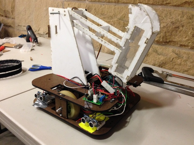
Figure 31: Robot with dunking arm and all other components attached
Still, integrating the systems did not immediately yield a working robot. After assembling our ‘bot, the two major remaining problems were imperfect dunking and inconsistent reverse speeds between the motors.
First, the dunking mechanism did not always end up scoring points, as the imprecision of the ultrasonic measurements would sometimes lead the ‘bot to attempt to dunk the balls when it was slightly off center. This was an easy fix, however, as we simply added parameters to the code to ensure that it was centered before it dunked. This task entailed creating a state in which the ‘bot had reached the end of the field, but was off-center. Then, when in this state, the ‘bot reverses, turns toward center, and moves forward again. In this way, we were able to solve the improper dunking problem, and ensure our ‘bot always scores!
Next, the inconsistency in the reverse state proved a bit more difficult to resolve. Though we experimented with more elegant solutions, we eventually found that the best way to solve this problem was to manually account for the differences in speed and add a corrective factor appropriately. Much like our process for making the robot drive straight when moving forward, this took many iterations. But after we discovered the correct factors, our final roadblock was cleared!
Final Product:
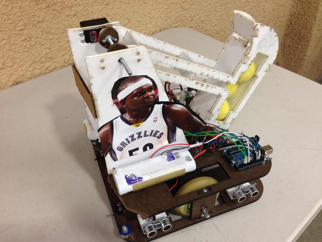
With these last two issues resolved, we performed a few final tests and determined that we had successfully achieved our goals. Thus, we proceeded to check-off with the teaching team to make it official! Updated relevant information can be found below. Figure 32 shows a ‘glamour shot’ of our robot, and Figure 33 depicts the final, functional product.
First, the dunking mechanism did not always end up scoring points, as the imprecision of the ultrasonic measurements would sometimes lead the ‘bot to attempt to dunk the balls when it was slightly off center. This was an easy fix, however, as we simply added parameters to the code to ensure that it was centered before it dunked. This task entailed creating a state in which the ‘bot had reached the end of the field, but was off-center. Then, when in this state, the ‘bot reverses, turns toward center, and moves forward again. In this way, we were able to solve the improper dunking problem, and ensure our ‘bot always scores!
Next, the inconsistency in the reverse state proved a bit more difficult to resolve. Though we experimented with more elegant solutions, we eventually found that the best way to solve this problem was to manually account for the differences in speed and add a corrective factor appropriately. Much like our process for making the robot drive straight when moving forward, this took many iterations. But after we discovered the correct factors, our final roadblock was cleared!
Final Product:
With these last two issues resolved, we performed a few final tests and determined that we had successfully achieved our goals. Thus, we proceeded to check-off with the teaching team to make it official! Updated relevant information can be found below. Figure 32 shows a ‘glamour shot’ of our robot, and Figure 33 depicts the final, functional product.
Final Arduino Code File:
| codebase_v17.ino |
Arduino Connections List:
Digital input pin connections:
Pins 2-5: Motor connections (Enable/Direction)
Pin 6: Rear bumper circuit
Pin 8: Front bumper circuit
Pins 9-10: Front ultrasonic circuit
Pins 11, 13: Rear ultrasonic circuit
Pin 12: Servo circuit
Digital input pin connections:
Pins 2-5: Motor connections (Enable/Direction)
Pin 6: Rear bumper circuit
Pin 8: Front bumper circuit
Pins 9-10: Front ultrasonic circuit
Pins 11, 13: Rear ultrasonic circuit
Pin 12: Servo circuit
Updated State Diagram:
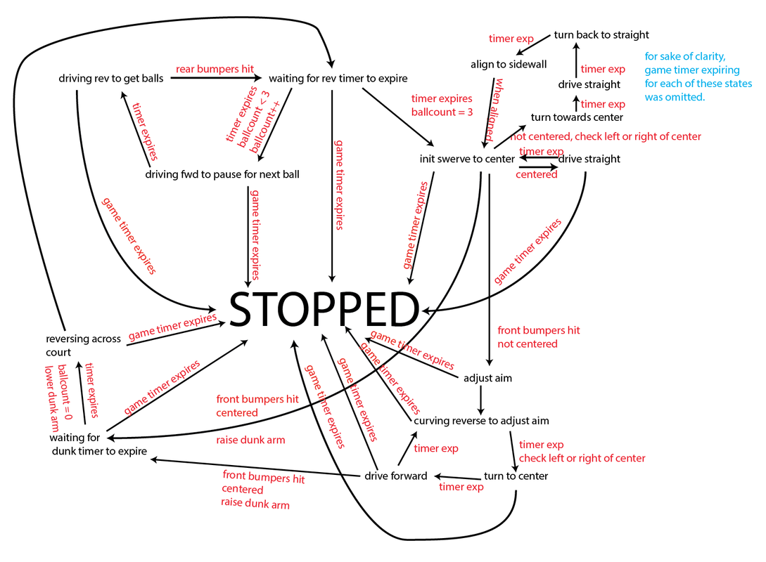
Figure 34: Our Final State Diagram
Bill of Materials:
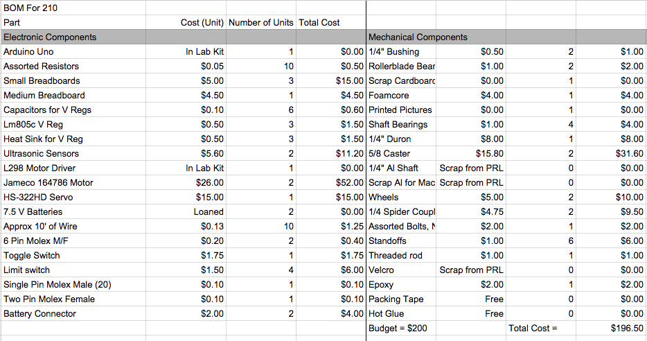
Figure 35: Bill of Materials
Eagle Schematic:
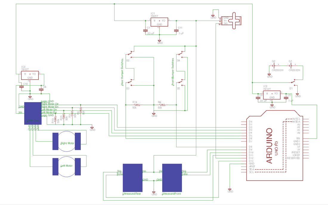
Figure 36: Eagle schematic of our entire circuit
Lessons Learned:
As with any project, our group asserts that we could complete the task much more quickly and smoothly a second time around. As such, we decided to structure our ‘lessons learned’ in the form of “The Ten (Plus 1) Commandments of ME210,” which are as follows:
As with any project, our group asserts that we could complete the task much more quickly and smoothly a second time around. As such, we decided to structure our ‘lessons learned’ in the form of “The Ten (Plus 1) Commandments of ME210,” which are as follows:
- Thou shalt put voltage regulators between batteries and all circuits.
- Thou shalt make all grounds common.
- Thou shalt look for recommended circuit wiring in all datasheets—particularly in regard to capacitors across voltage regulators.
- Thou shalt respect all maximum current draw specifications on power sources.
- Thou shalt ensure that systems are fully functional before trying to build on top of them—do not try to debug a poorly constructed drive-train.
- Thou shalt turn off all power before plugging things in. Unless you like fried components.
- Thou shalt clean all sensor signals with op-amps or comparators or both.
- Thou shalt tin or attach pins to wires that do not fit snugly in the breadboard.
- Thou shall not attempt to solder after 72 hours of wakefulness. Was this wire power or ground anyway…
- Thou shalt make wiring clean and obvious.
- Thou shall not leave floating logic pins. pull up or pull down. do it.
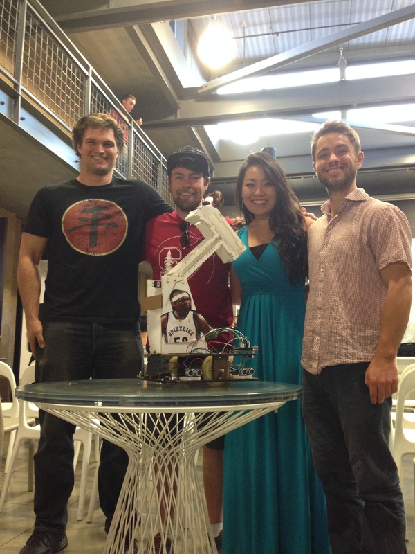
Figure 37: Team 12-Inch Grave on Presentation Day! (L-R: Jacob Gowan, Shane Clarkson, Joy Xi, Josh Feler)
